How Speedometers Work

By: William Harris  | 
A mechanical speedometer.
Photo courtesy of Dreamstime

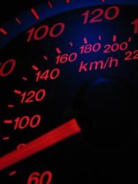
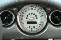
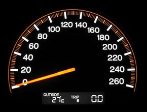
The dashboard instrument cluster in your car organizes a variety of sensors and gauges, including the oil pressure gauge, coolant temperature gauge, fuel level gauge, tachometer and more. But the most prominent gauge— and perhaps the most important, at least in terms of how many times you look at it while you're driving— is the speedometer. The job of the speedometer is to indicate the speed of your car in miles per hour, kilometers per hour or both. Analog speedometers use a needle to point to a specific speed, which the driver reads as a number printed on a dial.

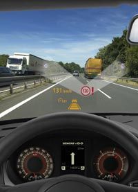
The first speedometers were expensive and available only as options. It wasn't until 1910 that automobile manufacturers began to include the speedometer as standard equipment. One of the first speedometer suppliers was Otto Schulze Autometer (OSA), a legacy company of Siemens VDO Automotive AG, one of the leading developers of modern instrument clusters. The first OSA speedometer was built in 1923 and its basic design didn't change significantly for 60 years. In this article, we're going to look at the history of speedometers, how they work and what the future may hold for speedometer design.

Advertisement

Types of Speedometers

The speedometer has gone through many changes in the last century.
Photo courtesy of Siemens VDO Automotive

­

­­

Advertisement

­There are two types of speedometers: electronic and mechanical. Because the electronic­ speedometer is a relatively new invention— the first all-electronic speedometer didn't appear until 1993— this article will focus primarily on the mechanical speedometeror the eddy-current speedometer.

Otto Schulze, an inventor from Germany, filed the first patent for the eddy-current speedometer in 1902. Schulze conceived of the revolutionary device as a solution to a growing problem. Not only were cars becoming more popular, but they were also traveling faster. The average automobile's top speed just after the turn of the 20th century was 30 miles per hour, slow by today's standards but sizzling fast at a time when much of the world still moved at the leisurely pace of a horse-drawn carriage. As a result, serious accidents began to increase dramatically.

Schulze's invention allowed drivers to see exactly how fast they were traveling and to make adjustments accordingly. At the same time, many countries established speed limits and used police officers to enforce them. Early solutions required automobiles to have speedometers with two dials— a small dial for the driver and a much larger dial mounted so police could read it from a distance.

In the next section, we'll look at this design to understand the parts of an eddy-current speedometer.

­

Eddy-Current Speedometer Parts

The needle of a speedometer
Photo used under the Creative Commons License 2.0

Before we take a look inside a speedometer, it will be helpful to review how a car works in the first place. The basic process is described below:

  1. Piston engines use energy from a burning fuel-air mixture to move a piston up and down in a cylinder.
  2. This reciprocating motion of the pistons is converted into rotary motion by a crankshaft.
  3. The crankshaft turns a flywheel.
  4. The transmission transmits power from the flywheel and directs it, through a driveshaft, to the wheels.
  5. The transmission has different gears— or speeds— to control how fast the wheels turn.
  6. As the wheels turn, they cause the car to move.

To measure the speed of a car, one must be able to measure the rotational speed of either the wheels or the transmission and send that information to some sort of gauge. In most cars, measurement takes place in the transmission. And the job of measuring the rotational speed generated by the transmission falls to something called a drive cable.

Advertisement

­

­The drive cable consists of a number of superimposed, tightly wound, helical coil springs wrapped around a center wire, or mandrel. Because of its construction, the drive cable is very flexible and can be bent, without fracture, to a very small radius. This is handy because the cable must snake its way from the transmission to the instrument cluster, which houses the speedometer. It is connected to a set of gears in the transmission, so that when the vehicle moves, the gears turn the mandrel inside the flexible shaft. The mandrel then communicates the rotational speed of the transmission down the length of the cable to the "business end" of the speedometer— where the speed measurement actually takes place.

The speedometer has other important parts, as well. The drive cable attaches, via a spiral gear, to a permanent magnet. The magnet sits inside a cup-shaped metal piece known as the speed cup. The speed cup is attached to a needle, which is held in place by a hairspring. The needle is visible in the cockpit of the car, as is the speedometer face, which displays a range of numbers from zero to an upper limit that can vary by make and model.

Now let's look at how this relatively simple device actually measures vehicle speed.

Eddy-Current Speedometer

An eddy current speedometer.
Photo courtesy of Dreamstime

Let's say a car is traveling along the highway at a constant speed. That means its transmission and driveshaft are rotating at a speed that corresponds to the vehicle's speed. It also means that the mandrel in the speedometer's drive cable— because it's connected to the transmission via a set of gears— is also rotating at the same speed. And, finally, the permanent magnet at the other end of the drive cable is rotating.

As the magnet spins, it sets up a rotating magnetic field, creating forces that act on the speed cup. These forces cause electrical current to flow in the cup in small rotating eddies, known as eddy currents. In some applications, eddy currents represent lost power and are therefore undesirable. But in the case of a speedometer, the eddy currents create a drag torque that does work on the speed cup. The cup and its attached needle turn in the same direction that the magnetic field is turning— but only as far as the hairspring will allow it. The needle on the speed cup comes to a rest where the opposing force of the hairspring balances the force created by the revolving magnet.

Advertisement

What if the car increases or decreases its speed? If the car travels faster, the permanent magnet inside the speed cup will rotate faster, which creates a stronger magnetic field, larger eddy currents and a greater deflection of the speedometer needle. If the car slows down, the magnet inside the cup rotates more slowly, which reduces the strength of the magnetic field, resulting in smaller eddy currents and less deflection of the needle. When a car is stopped, the hairspring holds the needle at zero.

Speedometer Calibration

All speedometers must be calibrated to make sure the torque created by the magnetic field accurately reflects the speed of the car. This calibration must take into account several factors, including the ratios of the gears in the drive cable, the final drive ratio in the differential and the diameter of the tires. All of these factors affect the overall speed of the vehicle. Take tire size, for example. When an axle makes one complete turn, the tire it's connected to makes one complete revolution. But a tire with a larger diameter will travel farther than a wheel with a smaller diameter. That's because the distance a tire covers in one revolution is equal to its circumference. So a tire with a diameter of 20 inches will cover about 62.8 inches of ground in one revolution. A tire with a diameter of 30 inches will cover more ground— about 94.2 inches.

Calibration adjusts for these variances and is done by the manufacturer, which sets up the speedometer gear to correspond with the factory-installed ring and pinion ratio and tire size. A car owner may have to recalibrate the speedometer if they make changes that make the vehicle fall out of factory specifications (see the sidebar below). Recalibrating a speedometer can be done by manipulating the hairspring, the permanent magnetor both. Generally, the strength of the magnetic field is the easiest variable to change. This requires a powerful electromagnet, which can be used to adjust the strength of the permanent magnet in the speedometer until the needle matches the input from the rotating drive cable.

Advertisement

The Future of Speedometer Design

A head-up speedometer display
Photo courtesy of Siemens VDO Automotive

­­One of the big disadvantages of early instrument clusters was the location. A driver had to look down to see the dials, taking their eyes off the road for at least one second. In that one second, the car travels about 46 feet if it's moving at 30 miles per hour.

In 2003, Siemens VDO developed a head-up display projected onto the windshield by mirrors. To the driver, this display appears to float above the engine hood, about six feet away. Vehicle speed is one of the key elements of the display, but it also contains any element found in a normal instrument cluster. It can also integrate orientation aids that use images from infrared cameras to detect and display an outline of the road ahead. For a technology that dates back almost 100 years, that was a significant change for the better.

Advertisement

For more information on speedometers, cars and related topics, check out the links on the next page.

­

Lots More Information

­Related HowStuffWorks Articles

Sources

  • “100 Years of Speedometers — The History of Driver Information,” November 7, 2002. Found online at: http://www.siemensvdo.com/press/releases/interior/2002/SV-200211-009-e.htm.
  • “Automating Speedometer Calibration,” by Ganesh Devaraj, S.B. Rajnarayanan, A. Senthilnathan and S.R. Anand. Evaluation Engineering. Found online at http://www.evaluationengineering.com/archive/articles/1100auto.htm.
  • Encyclopedia Britannica 2005, s.v. “eddy current.” CD-ROM, 2005.
  • Encyclopedia Britannica 2005, s.v. “flexible shaft.” CD-ROM, 2005.
  • Encyclopedia Britannica 2005, s.v. “tachometer.” CD-ROM, 2005.
  • Erjavec, Jack. "Automotive Technology: A Systems Approach." New York: Thomson Delmar Learning. 2005.
  • “From speedometers to modern instrument clusters,” by Gerhard Wesner. Automotive Engineering International, January 2005. PDF download at www.sae.org/automag/features/futurelook/02-2005/1-113-2-89.pdf
  • Inner Auto Parts Web Site:http://www.innerauto.com/Automotive_Systems/Drive_Train/Speedometer~odometer/ http://www.innerauto.com/Automotive_Systems/Drive_Train/Speedometer_Cable/
  • Miata.net Tire Size Calculator http://www.miata.net/garage/tirecalc.html
  • The National Watch and Clock Museum http://www.nawcc.org/museum/museum.htm
  • Siemens VDO Automotive Web Site http://www.siemensvdo.com