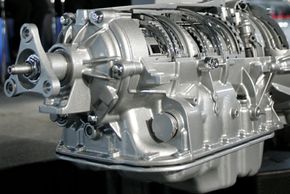
The 6L50 transmission is a Hydra-Matic six-speed rear and all-wheel drive automatic transmission produced by GM.
Bill Pugliano/Getty Images
If you have ever driven a car with an automatic transmission, then you know that there are two big differences between an automatic transmission and a manual transmission:
There is no clutch pedal in an automatic transmission car.
There is no gear shift in an automatic transmission car. Once you put the transmission into drive, everything else is automatic.
Both the automatic transmission (plus its torque converter) and a manual transmission (with its clutch) accomplish exactly the same thing, but they do it in totally different ways. It turns out that the way an automatic transmission does it is absolutely amazing!
Advertisement
In this article, we'll work our way through an automatic transmission. We'll start with the key to the whole system: planetary gearsets. Then we'll see how the transmission is put together, learn how the controls work and discuss some of the intricacies involved in controlling a transmission.
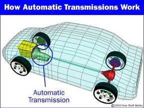
Just like that of a manual transmission, the automatic transmission's primary job is to allow the engine to operate in its narrow range of speeds while providing a wide range of output speeds.
Without a transmission, cars would be limited to one gear ratio, and that ratio would have to be selected to allow the car to travel at the desired top speed. If you wanted a top speed of 80 mph, then the gear ratio would be similar to third gear in most manual transmission cars.
Advertisement
You've probably never tried driving a manual transmission car using only third gear. If you did, you'd quickly find out that you had almost no acceleration when starting out, and at high speeds, the engine would be screaming along near the red-line. A car like this would wear out very quickly and would be nearly undriveable.
So the transmission uses gears to make more effective use of the engine's torque, and to keep the engine operating at an appropriate speed. When towing or hauling heavy objects, your vehicle's transmission can get hot enough to burn up the transmission fluid. In order to protect the transmission from serious damage, drivers who tow should buy vehicles equipped with transmission coolers.
The key difference between a manual and an automatic transmission is that the manual transmission locks and unlocks different sets of gears to the output shaft to achieve the various gear ratios, while in an automatic transmission, the same set of gears produces all of the different gear ratios. The planetary gearset is the device that makes this possible in an automatic transmission.
Let's take a look at how the planetary gearset works.
Advertisement
The Planetary Gearset
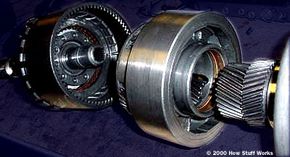
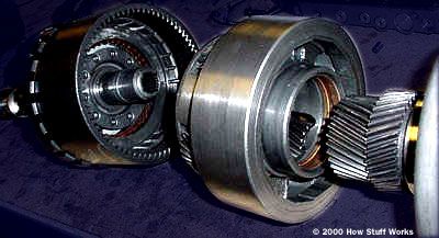
From left to right: the ring gear, planet carrier, and two sun gears
When you take apart and look inside an automatic transmission, you find a huge assortment of parts in a fairly small space. Among other things, you see:
An ingenious planetary gearset
A set of bands to lock parts of a gearset
A set of three wet-plate clutches to lock other parts of the gearset
An incredibly odd hydraulic system that controls the clutches and bands
A large gear pump to move transmission fluid around
The center of attention is the planetary gearset. About the size of a cantaloupe, this one part creates all of the different gear ratios that the transmission can produce. Everything else in the transmission is there to help the planetary gearset do its thing. This amazing piece of gearing has appeared on HowStuffWorks before. You may recognize it from the electric screwdriver article. An automatic transmission contains two complete planetary gearsets folded together into one component. See How Gear Ratios Work for an introduction to planetary gearsets.
Advertisement
Any planetary gearset has three main components:
The sun gear
The planet gears and the planet gears' carrier
The ring gear
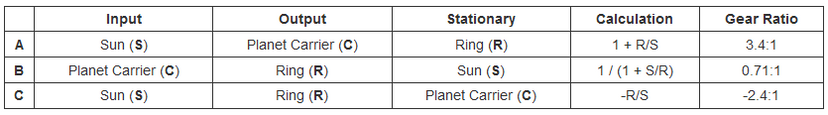
Each of these three components can be the input, the output or can be held stationary. Choosing which piece plays which role determines the gear ratio for the gearset. Let's take a look at a single planetary gearset.
Advertisement
Planetary Gearset Ratios
One of the planetary gearsets from our transmission has a ring gear with 72 teeth and a sun gear with 30 teeth. We can get lots of different gear ratios out of this gearset.
Also, locking any two of the three components together will lock up the whole device at a 1:1 gear reduction. Notice that the first gear ratio listed above is a reduction -- the output speed is slower than the input speed. The second is an overdrive -- the output speed is faster than the input speed. The last is a reduction again, but the output direction is reversed. There are several other ratios that can be gotten out of this planetary gear set, but these are the ones that are relevant to our automatic transmission. You can see them in the animation below:
Advertisement
So this one set of gears can produce all of these different gear ratios without having to engage or disengage any other gears. With two of these gearsets in a row, we can get the four forward gears and one reverse gear our transmission needs. We'll put the two sets of gears together in the next section.
Advertisement
Compound Planetary Gearset
This automatic transmission uses a set of gears, called a compound planetary gearset, that looks like a single planetary gearset but actually behaves like two planetary gearsets combined. It has one ring gear that is always the output of the transmission, but it has two sun gears and two sets of planets.
Let's look at some of the parts:
Advertisement
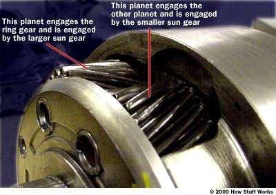
A compound planetary gearset acts like two planetary gearsets combined. Learn about compound planetary gearsets and an automatic transmissions structure.
The figure below shows the planets in the planet carrier. Notice how the planet on the right sits lower than the planet on the left. The planet on the right does not engage the ring gear — it engages the other planet. Only the planet on the left engages the ring gear.
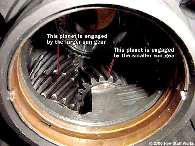
A compound planetary gearset acts like two planetary gearsets combined. Learn about compound planetary gearsets and an automatic transmissions structure.
Next you can see the inside of the planet carrier. The shorter gears are engaged only by the smaller sun gear. The longer planets are engaged by the bigger sun gear and by the smaller planets.
A compound planetary gearset acts like two planetary gearsets combined. Learn about compound planetary gearsets and an automatic transmissions structure.
The animation below shows how all of the parts are hooked up in a transmission.
Advertisement
First Gear
In first gear, the smaller sun gear is driven clockwise by the turbine in the torque converter. The planet carrier tries to spin counterclockwise, but is held still by the one-way clutch (which only allows rotation in the clockwise direction) and the ring gear turns the output. The small gear has 30 teeth and the ring gear has 72, so the gear ratio is:
Ratio = -R/S = - 72/30 = -2.4:1
Advertisement
So the rotation is negative 2.4:1, which means that the output direction would be opposite the input direction. But the output direction is really the same as the input direction -- this is where the trick with the two sets of planets comes in. The first set of planets engages the second set, and the second set turns the ring gear; this combination reverses the direction. You can see that this would also cause the bigger sun gear to spin; but because that clutch is released, the bigger sun gear is free to spin in the opposite direction of the turbine (counterclockwise).
Second Gear
This transmission does something really neat in order to get the ratio needed for second gear. It acts like two planetary gearsets connected to each other with a common planet carrier.
The first stage of the planet carrier actually uses the larger sun gear as the ring gear. So the first stage consists of the sun (the smaller sun gear), the planet carrier, and the ring (the larger sun gear).
Advertisement
The input is the small sun gear; the ring gear (large sun gear) is held stationary by the band, and the output is the planet carrier. For this stage, with the sun as input, planet carrier as output, and the ring gear fixed, the formula is:
1 + R/S = 1 + 36/30 = 2.2:1
The planet carrier turns 2.2 times for each rotation of the small sun gear. At the second stage, the planet carrier acts as the input for the second planetary gear set, the larger sun gear (which is held stationary) acts as the sun, and the ring gear acts as the output, so the gear ratio is:
1 / (1 + S/R) = 1 / (1 + 36/72) = 0.67:1
To get the overall reduction for second gear, we multiply the first stage by the second, 2.2 x 0.67, to get a 1.47:1 reduction.
Advertisement
Third Gear
Most automatic transmissions have a 1:1 ratio in third gear. You'll remember from the previous section that all we have to do to get a 1:1 output is lock together any two of the three parts of the planetary gear. With the arrangement in this gearset it is even easier — all we have to do is engage the clutches that lock each of the sun gears to the turbine.
If both sun gears turn in the same direction, the planet gears lockup because they can only spin in opposite directions. This locks the ring gear to the planets and causes everything to spin as a unit, producing a 1:1 ratio.
Advertisement
Overdrive
By definition, an overdrive has a faster output speed than input speed. It's a speed increase — the opposite of a reduction. In this transmission, engaging the overdrive accomplishes two things at once. If you read How Torque Converters Work, you learned about lockup torque converters. In order to improve efficiency, some cars have a mechanism that locks up the torque converter so that the output of the engine goes straight to the transmission.
In this transmission, when overdrive is engaged, a shaft that is attached to the housing of the torque converter (which is bolted to the flywheel of the engine) is connected by clutch to the planet carrier. The small sun gear freewheels, and the larger sun gear is held by the overdrive band. Nothing is connected to the turbine; the only input comes from the converter housing. Let's go back to our chart again, this time with the planet carrier for input, the sun gear fixed and the ring gear for output.
Advertisement
Ratio = 1 / (1 + S/R) = 1 / ( 1 + 36/72) = 0.67:1
So the output spins once for every two-thirds of a rotation of the engine. If the engine is turning at 2000 rotations per minute (RPM), the output speed is 3000 RPM. This allows cars to drive at freeway speed while the engine speed stays nice and slow.
Advertisement
Reverse Gear
Reverse is very similar to first gear, except that instead of the small sun gear being driven by the torque converter turbine, the bigger sun gear is driven, and the small one freewheels in the opposite direction. The planet carrier is held by the reverse band to the housing. So, according to our equations from the last page, we have:
So the ratio in reverse is a little less than first gear in this transmission.
Advertisement
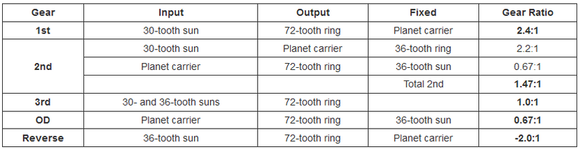
Gear Ratios
This transmission has four forward gears and one reverse gear. Let's summarize the gear ratios, inputs and outputs:
After reading these sections, you are probably wondering how the different inputs get connected and disconnected. This is done by a series of clutches and bands inside the transmission. In the next section, we'll see how these work.
Advertisement
Clutches and Bands in an Automatic Transmission
In the last section, we discussed how each of the gear ratios is created by the transmission. For instance, when we discussed overdrive, we said:
In this transmission, when overdrive is engaged, a shaft that is attached to the housing of the torque converter (which is bolted to the flywheel of the engine) is connected by clutch to the planet carrier. The small sun gear freewheels, and the larger sun gear is held by the overdrive band. Nothing is connected to the turbine; the only input comes from the converter housing.
To get the transmission into overdrive, lots of things have to be connected and disconnected by clutches and bands. The planet carrier gets connected to the torque converter housing by a clutch. The small sun gets disconnected from the turbine by a clutch so that it can freewheel. The big sun gear is held to the housing by a band so that it could not rotate. Each gear shift triggers a series of events like these, with different clutches and bands engaging and disengaging. Let's take a look at a band.
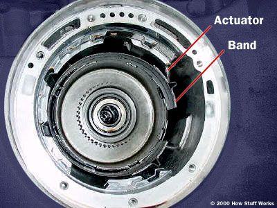
Bands
In this transmission there are two bands. The bands in a transmission are, literally, steel bands that wrap around sections of the gear train and connect to the housing. They are actuated by hydraulic cylinders inside the case of the transmission.
In the figure above, you can see one of the bands in the housing of the transmission. The gear train is removed. The metal rod is connected to the piston, which actuates the band.
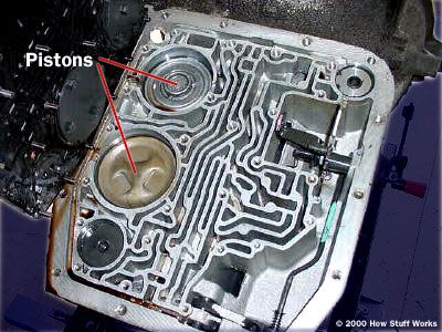
The pistons that actuate the bands are visible here.
Above you can see the two pistons that actuate the bands. Hydraulic pressure, routed into the cylinder by a set of valves, causes the pistons to push on the bands, locking that part of the gear train to the housing.
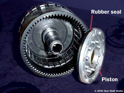
The clutches in the transmission are a little more complex. In this transmission there are four clutches. Each clutch is actuated by pressurized hydraulic fluid that enters a piston inside the clutch. Springs make sure that the clutch releases when the pressure is reduced. Below you can see the piston and the clutch drum. Notice the rubber seal on the piston -- this is one of the components that is replaced when your transmission gets rebuilt.
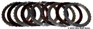
The next figure shows the alternating layers of clutch friction material and steel plates. The friction material is splined on the inside, where it locks to one of the gears. The steel plate is splined on the outside, where it locks to the clutch housing. These clutch plates are also replaced when the transmission is rebuilt.
The pressure for the clutches is fed through passageways in the shafts. The hydraulic system controls which clutches and bands are energized at any given moment.
When You Put the Car in Park
It may seem like a simple thing to lock the transmission and keep it from spinning, but there are actually some complex requirements for this mechanism. First, you have to be able to disengage it when the car is on a hill (the weight of the car is resting on the mechanism). Second, you have to be able to engage the mechanism even if the lever does not line up with the gear. Third, once engaged, something has to prevent the lever from popping up and disengaging.
The mechanism that does all this is pretty neat. Let's look at some of the parts first.
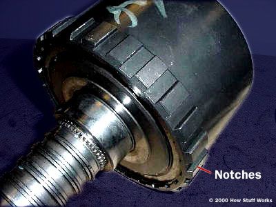
The output of the transmission: The square notches are engaged by the parking-brake mechanism to hold the car still.
The parking-brake mechanism engages the teeth on the output to hold the car still. This is the section of the transmission that hooks up to the drive shaft -- so if this part can't spin, the car can't move.
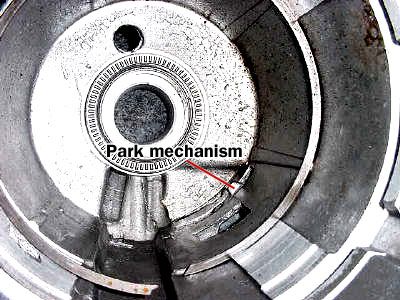
The empty housing of the transmission with the parking brake mechanism poking through, as it does when the car is in park
Above you see the parking mechanism protruding into the housing where the gears are located. Notice that it has tapered sides. This helps to disengage the parking brake when you are parked on a hill -- the force from the weight of the car helps to push the parking mechanism out of place because of the angle of the taper.
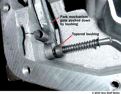
When the shift lever is placed in park, the rod pushes the spring against the small tapered bushing. If the park mechanism is lined up so that it can drop into one of the notches in the output gear section, the tapered bushing will push the mechanism down. If the mechanism is lined up on one of the high spots on the output, then the spring will push on the tapered bushing, but the lever will not lock into place until the car rolls a little and the teeth line up properly. This is why sometimes your car moves a little bit after you put it in park and release the brake pedal -- it has to roll a little for the teeth to line up to where the parking mechanism can drop into place.
Once the car is safely in park, the bushing holds down the lever so that the car will not pop out of park if it is on a hill.
Automatic Transmissions: Hydraulics, Pumps and the Governor
Hydraulics
The automatic transmission in your car has to do numerous tasks. You may not realize how many different ways it operates. For instance, here are some of the features of an automatic transmission:
If the car is in overdrive (on a four-speed transmission), the transmission will automatically select the gear based on vehicle speed and throttle pedal position.
If you accelerate gently, shifts will occur at lower speeds than if you accelerate at full throttle.
If you floor the gas pedal, the transmission will downshift to the next lower gear.
If you move the shift selector to a lower gear, the transmission will downshift unless the car is going too fast for that gear. If the car is going too fast, it will wait until the car slows down and then downshift.
If you put the transmission in second gear, it will never downshift or upshift out of second, even from a complete stop, unless you move the shift lever.
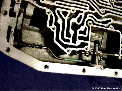
You've probably seen something that looks like this before. It is really the brain of the automatic transmission, managing all of these functions and more. The passageways you can see route fluid to all the different components in the transmission. Passageways molded into the metal are an efficient way to route fluid; without them, many hoses would be needed to connect the various parts of the transmission. First, we'll discuss the key components of the hydraulic system; then we'll see how they work together.
Automatic transmissions have a neat pump, called a gear pump. The pump is usually located in the cover of the transmission. It draws fluid from a sump in the bottom of the transmission and feeds it to the hydraulic system. It also feeds the transmission cooler and the torque converter.
The inner gear of the pump hooks up to the housing of the torque converter, so it spins at the same speed as the engine. The outer gear is turned by the inner gear, and as the gears rotate, fluid is drawn up from the sump on one side of the crescent and forced out into the hydraulic system on the other side.
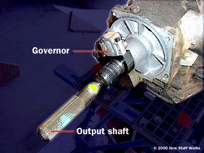
The Governor
The governor is a clever valve that tells the transmission how fast the car is going. It is connected to the output, so the faster the car moves, the faster the governor spins. Inside the governor is a spring-loaded valve that opens in proportion to how fast the governor is spinning -- the faster the governor spins, the more the valve opens. Fluid from the pump is fed to the governor through the output shaft.
The faster the car goes, the more the governor valve opens and the higher the pressure of the fluid it lets through.
To shift properly, the automatic transmission has to know how hard the engine is working. There are two different ways that this is done. Some cars have a simple cable linkage connected to a throttle valve in the transmission. The further the gas pedal is pressed, the more pressure is put on the throttle valve. Other cars use a vacuum modulator to apply pressure to the throttle valve. The modulator senses the manifold pressure, which increases when the engine is under a greater load.
The manual valve is what the shift lever hooks up to. Depending on which gear is selected, the manual valve feeds hydraulic circuits that inhibit certain gears. For instance, if the shift lever is in third gear, it feeds a circuit that prevents overdrive from engaging.
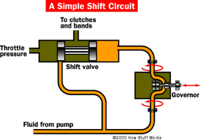
Shift valves supply hydraulic pressure to the clutches and bands to engage each gear. The valve body of the transmission contains several shift valves. The shift valve determines when to shift from one gear to the next. For instance, the 1 to 2 shift valve determines when to shift from first to second gear. The shift valve is pressurized with fluid from the governor on one side, and the throttle valve on the other. They are supplied with fluid by the pump, and they route that fluid to one of two circuits to control which gear the car runs in.
The shift valve will delay a shift if the car is accelerating quickly. If the car accelerates gently, the shift will occur at a lower speed. Let's discuss what happens when the car accelerates gently.
As car speed increases, the pressure from the governor builds. This forces the shift valve over until the first gear circuit is closed, and the second gear circuit opens. Since the car is accelerating at light throttle, the throttle valve does not apply much pressure against the shift valve.
When the car accelerates quickly, the throttle valve applies more pressure against the shift valve. This means that the pressure from the governor has to be higher (and therefore the vehicle speed has to be faster) before the shift valve moves over far enough to engage second gear.
Each shift valve responds to a particular pressure range; so when the car is going faster, the 2-to-3 shift valve will take over, because the pressure from the governor is high enough to trigger that valve.
Electronically Controlled Transmissions
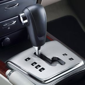
An automatic transmission with a manual mode allows the driver to shift gears without a clutch pedal.
Electronically controlled transmissions, which appear on some newer cars, still use hydraulics to actuate the clutches and bands, but each hydraulic circuit is controlled by an electric solenoid. This simplifies the plumbing on the transmission and allows for more advanced control schemes.
In the last section we saw some of the control strategies that mechanically controlled transmissions use. Electronically controlled transmissions have even more elaborate control schemes. In addition to monitoring vehicle speed and throttle position, the transmission controller can monitor the engine speed, if the brake pedal is being pressed, and even the anti-lock braking system.
Using this information and an advanced control strategy based on fuzzy logic -- a method of programming control systems using human-type reasoning -- electronically controlled transmissions can do things like:
Downshift automatically when going downhill to control speed and reduce wear on the brakes
Upshift when braking on a slippery surface to reduce the braking torque applied by the engine
Inhibit the upshift when going into a turn on a winding road
Let's talk about that last feature -- inhibiting the upshift when going into a turn on a winding road. Let's say you're driving on an uphill, winding mountain road. When you are driving on the straight sections of the road, the transmission shifts into second gear to give you enough acceleration and hill-climbing power. When you come to a curve you slow down, taking your foot off the gas pedal and possibly applying the brake. Most transmissions will upshift to third gear, or even overdrive, when you take your foot off the gas. Then when you accelerate out of the curve, they will downshift again. But if you were driving a manual transmission car, you would probably leave the car in the same gear the whole time. Some automatic transmissions with advanced control systems can detect this situation after you have gone around a couple of the curves, and "learn" not to upshift again.
For more information on automatic transmissions and related topics, check out the links that follow.
Automatic Transmission FAQ
What’s the main differences between an automatic transmission and a manuÂal transmission?
There are two main differences between an automatic transmission and a manuÂal transmission. First, there is no clutch pedal in an automatic transmission car. Second, there is no gear shift in an automatic transmission car, so once you put the transmission into drive, everything else is automatic.
What is the primary job of an automatic transmission?
The primary job of an automatic transmission is to allow the engine to operate in its narrow range of speeds while providing a wide range of output speeds.
When did automatic transmission become standard?
According to Sixt, automatic transmissions became the U.S. standard in the late 1980s.
How does an automatic transmission work?
According to Driving.ca, "[a]n automatic transmission uses sensors to determine when it should shift gears, and changes them using internal oil pressure."
What is inside an automatic transmission?
The inside of an automatic transmission has a planetary gearset, a set of bands, a set of three wet-plate clutches, a hydraulic system, and a large gear pump.